Imagicle Digital Fax interacts with the telephony system through SIP or H.323 protocols using either T.38 or G.711 passthrough modes.
The h.323 configuration is suggested and will be detailed. Remember to enable h.323 in the Digital Fax ⇒ Application Settings ⇒ IP Routes page on the Application Suite.
In the following examples, we are supposing UC Suite server IP address is 192.45.90.15.
Supported Avaya Telephony Platforms
- Avaya Communication Manager: rel.5.2 Service Pack 9 up to rel. 8.0 ⇒ H.323
- Avaya Aura rel. 8.x and above ⇒ SIP
- Avaya Media Gateway G250, firmware release: 30.18.1
- Avaya IP Office rel 7.x and above
Note: on CM 5.2.1 SP 8 and MG 30.12.1 you must force T.38 for outgoing faxes
Avaya Communication Manager Configuration
In this configuration, Digital Fax directly sends and receives h.323 calls directly from the PBX. It will use t.38 to transport the t.30 fax data.
On the Avaya PBX you must configure an h.323 trunk pointing to the UC Suite server.
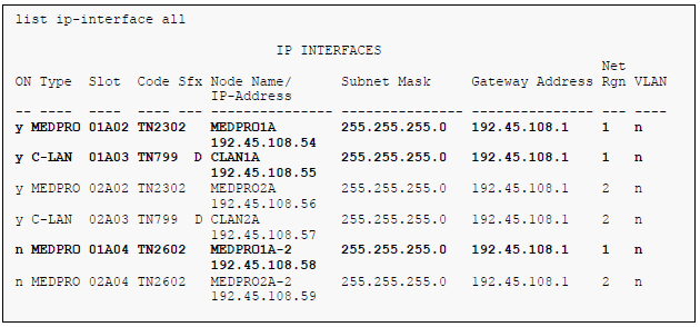
1. IP Interfaces
Use the list ip-interface all command to identify which IP interfaces are located in which network region. The example below shows the IP interfaces in our test installation. All interfaces in cabinet 01 (port network 1) as indicated in the Slot field are in IP network region 1 as indicated in the Net Rgn field.
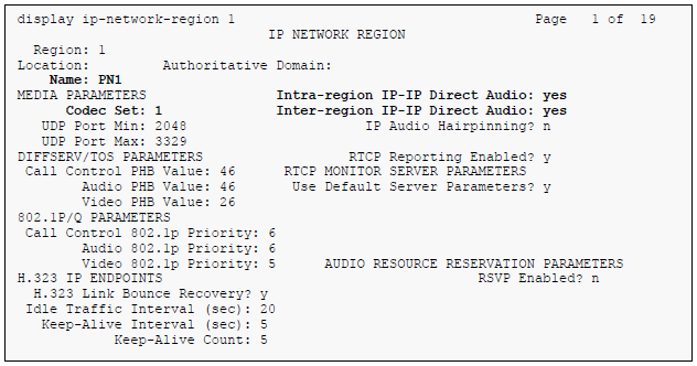
2. IP Network Region – Region 1
The configuration of the IP network regions (Steps 2 – 5) is assumed to already to be in place but is included here for clarity. In our example, the Avaya S8500 Server, the Avaya G650 Media Gateway comprising port network 1 and all IP endpoints were located in IP network region 1 using the parameters described below. Use the display ip-network-region command to view these settings. The example below shows the values used for the compliance test.
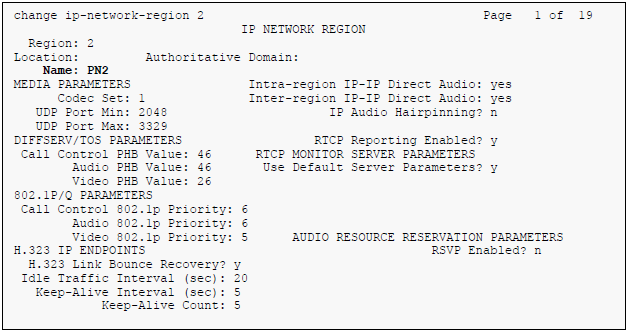
- A descriptive name was entered for the Name field
- IP-IP Direct Audio (shuffling) was enabled to allow audio traffic to be sent directly between IP endpoints without using media resources in the Avaya Media Gateway. This was done for both intra-region and inter-region IP-IP Direct Audio. This is the default setting. Shuffling can be further restricted at the trunk level on the Signaling Group form
- The Codec Set field was set to the IP codec set to be used for calls within this IP network region. In this case, IP codec set 1 was selected
- The default values were used for all other fields.
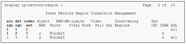
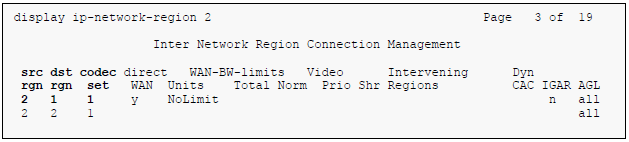
On Page 3, codec sets are defined for inter-region calls. In the case of the compliance test at site 1, calls from IP network region 1 (src rgn 1) to IP network region 2 (dst rgn 2) used codec set 1. The default values were used for all other fields. At site 2, only one IP network region exists so no inter-region settings were required.
3. IP Network Region –Region 2
At site 1, IP network region 2 was created in a similar manner as IP network region 1 but with a different name.
4. IP network region –Port Network 2
The inter-region codec setting was created similarly:
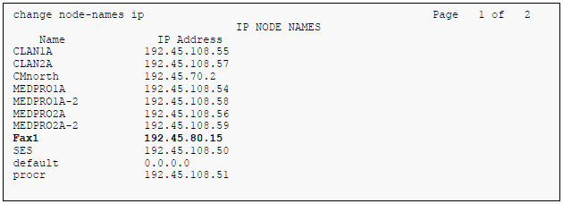
5. Ip Node Names
Use the change node-names command to create a node name that maps to UC Suite server IP address. This node name is used in the configuration of the H.323 trunk signaling group. The example below shows the entry on Avaya Communication Manager at site 1.
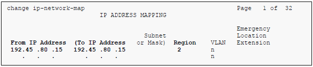
6. IP Network Map
If the UC Suite server should be located in an IP network region other than the default region of 1, then the region is assigned using the change ip-network-map command.
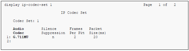
7. Codecs
Use the change ip-codec-set command to verify that G.711A or G.711MU is contained in the codec list.
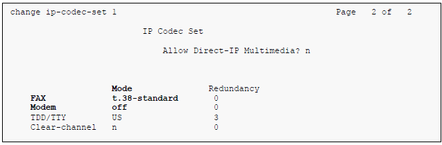
8. Fax
On Page 2, verify that the FAX Mode field is set to t.38-standard. This is necessary to support UC Suite server added to port network 2. The Modem Mode field should be set to off.
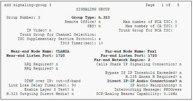
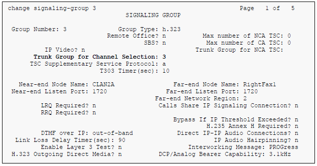
9. Signaling Group
Use the add signaling group command to create a signaling group for use by the H.323 trunk to UC Suite server. For the compliance test at site 1, signaling group 3 was configured using the parameters highlighted below. Default values may be used for all other fields.
- Set the Group Type to h.323
- The Trunk Group for Channel Selection is left blank until the trunk group is created. It will be updated later
- Set the Near-end Node Name to the node name that maps to the IP address of the CLAN circuit pack used to connect to UC Suite server. Node names are defined using the change node-names ip command. For site 2, this node name would map to the IP address of the Avaya Media Server (procr).
- Set the Far-end Node Name to the node name that maps to the IP address of UC Suite server.
- Set the Near-end Listen Port and Far-end Listen Port to 1720.
- Set the Far-end Network Region to the IP network region which contains Digital Fax
- Set the Direct IP-IP Audio Connections field to n. This field must be set to n for interoperability with Digital Fax
- The default values were used for all other fields.
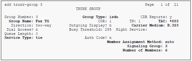
10. Trunk Group
Use the add trunk group command to create a trunk group for the H.323 trunk to the UC Suite server. In our example at site 1, trunk group 3 was configured using the parameters highlighted below. Default values may be used for all other fields.
On Page 1:
- Set the Group Type field to isdn
- Enter a descriptive name for the Group Name
- Enter an available trunk access code (TAC) that is consistent with the existing dial plan in the TAC field
- Set the Carrier Medium to H.323
- Set the Service Type field to tie
- Set the Member Assignment Method to auto
- Set the Signaling Group to the signaling group shown in the previous step
- In Number of Members field, enter the number of trunks in the trunk group. This determines how many simultaneous calls can be supported by the configuration
- Default values may be used for all other fields
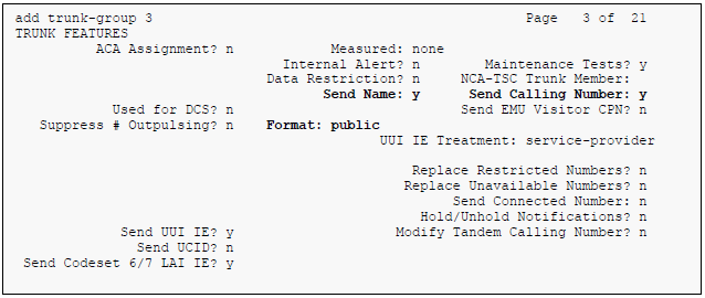
On Page 3:
- Set the Send Name field and Send Calling Number field to y. The enables sending calling party name and number to the far end
- Set the Numbering Format field to public. This field specifies the format of the calling party number sent to the far-end
- Default values may be used for all other fields
11. Signaling Group – Update
Use the change signaling-group command to update the Trunk Group for Channel Selection field with the trunk group created in the previous step.
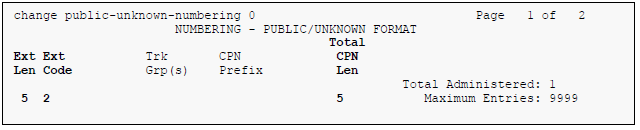
12. Public Unknown Numbering
Public unknown numbering defines the calling party number to be sent to the far-end. Use the change public-unknown-numbering command to create an entry that will be used by the trunk group defined in Step 3. In the example shown below, all calls originating from a 5-digit extension beginning with 2 and routed across any trunk group (Trk Grp column is blank) will be sent as a 5-digit calling number.
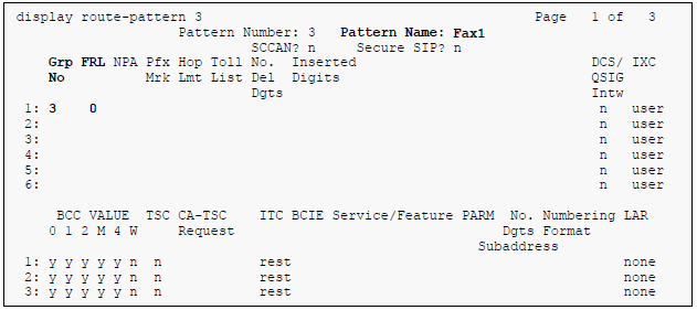
13. Route Pattern
Use the change route-pattern command to create a route pattern that will route calls to the H.323 trunk that connects to Digital Fax.
The example below shows the route pattern at site 1. A descriptive name was entered for the Pattern Name field. The Grp No field was set to the trunk group created in Step 10. The Facility Restriction Level (FRL) field was set to a level that allows access to this trunk for all users that require it. The value of 0 is the least restrictive level. The default values were used for all other fields.
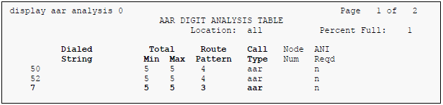
14. Routing Calls to Digital Fax
Automatic Alternate Routing (AAR) was used to route calls to Digital Fax. Use the change aar analysis command to create an entry in the AAR Digit Analysis Table for this purpose. The example below shows entries previously created for site 1 using the display aar analysis command. The highlighted entry specifies that numbers that begin with 7 and are 5 digits long, use route pattern 3. Route pattern 3 routes calls to Digital Fax.