Configuring Fortinet Next Generation Firewall
Version tested: Fortinet Next Generation Firewall version FortiOS 7.2
In this section we will refer to the configuration file you obtained from our UCCS Onboarding teams as “template conf” and will explain how to use its contents for configuring FortiOS 7.2.
As a reference for this guide, here is the full AWS file: FortiOS 6.4.4+ ikev2 (dynamic).txt
Interface names in AWS template are too long and need to be adjusted.
Create VPN Tunnels
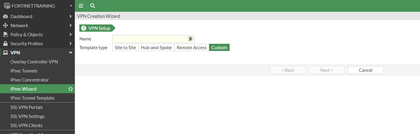
To create VPN Tunnels go to VPN > IPSec Tunnels > click “Create New”
The VPN Creation Wizard appears, select “Custom” and click Next:
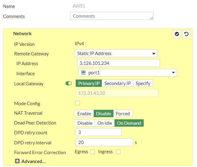
Configure the tunnel as specified in the template conf #1 Internet Key Exchange (IKE) Configuration
a. IP Version: IPv4
b. Remote Gateway: Static IP Address
c. IP address: 3.126.101.234
d. Local Interface: wan1
e. Local Gateway: Select Specify and enter WAN port IP (Public IP)
f. Dead Peer Detection: Enable by selecting On Idle/ On Demand
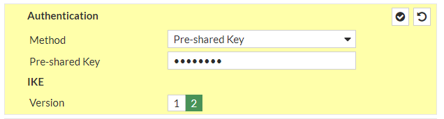
g. Authentication Method: Pre-shared Key
h. Pre-Shared Key: knJNjlMhl9b1Ydt8V7xHxPeGp_gRGIvF
i. IKE Version: 2
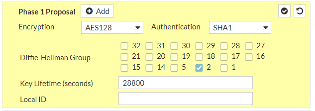
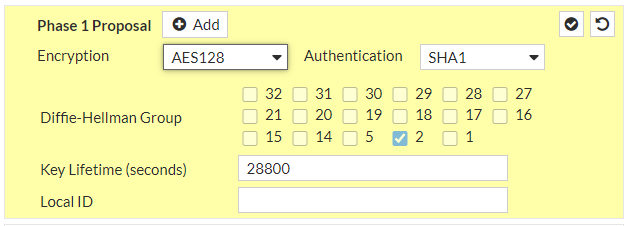
Phase 1 Proposal:
j. Encryption: aes128
k. Authentication: sha1
l. DH group: 2 ! and deselect 5
m. Keylife: 28800 seconds
and continue with #2: IPSec Configuration
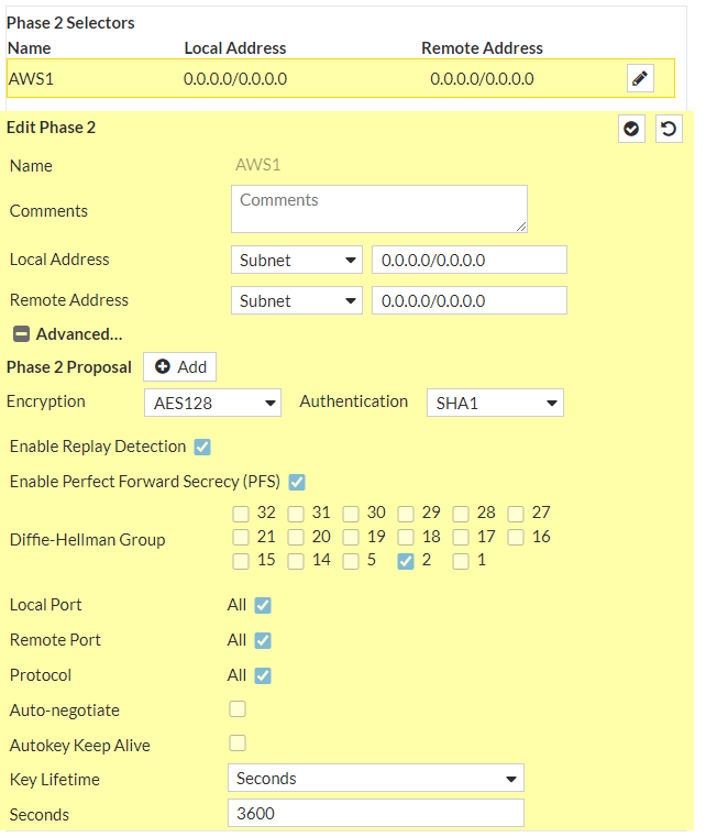
Under Phase 2 Selectors --> New Phase 2
a. Name: vpn-093bd262ad8d9a8b4-0
b. Local Address: LAN subnet behind Fortigate/0.0.0.0/0
c. Remote Address: AWS Private Subnet/0.0.0.0/0
Under Advanced
d. Encryption: aes128
e. Authentication: sha1
f. Select Enable Replay Detection
g. Select Perfect Forward Secrecy
h. DH Group: 2 ! and deselect 5
i. Keylife: 3600 seconds
j. Enable Auto-negotiate ! Autokey Keep Alive is enabled automatically when Auto-negotiate is enabled
k. Click Ok
and let’s do the same also for the IPSec Tunnel #2
a. IP Version: IPv4
b. Remote Gateway: Static IP Address
c. IP address: 35.156.84.84
d. Local Interface: wan1
e. Local Gateway: Select Specify and enter WAN port IP (Public IP)
f. Dead Peer Detection: Enable by selecting On Idle/ On Demand
g. Authentication Method: Pre-shared Key
h. Pre-Shared Key: UUegcCakIsG7BnxbhROo0S0ZPUYOvEYS
i. IKE Version: 2
Phase 1 Proposal:
j. Encryption: aes128
k. Authentication: sha1
l. DH group: 2 ! and deselect 5
m. Keylife: 28800 seconds

and
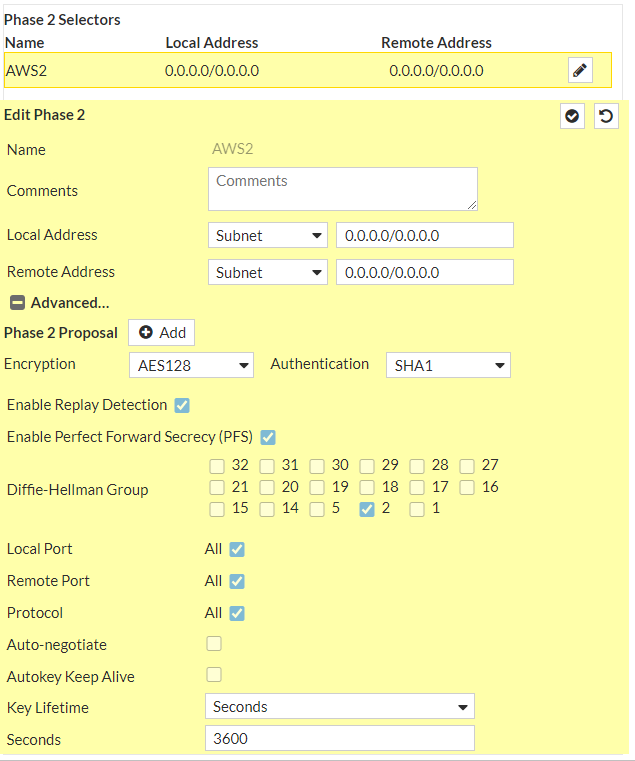
Under Phase 2 Selectors --> New Phase 2
a. Name: vpn-093bd262ad8d9a8b4-1
b. Local Address: LAN subnet behind Fortigate/0.0.0.0/0
c. Remote Address: AWS Private Subnet/0.0.0.0/0
Under Advanced
d. Encryption: aes128
e. Authentication: sha1
f. Select Enable Replay Detection
g. Select Perfect Forward Secrecy
h. DH Group: 2 ! and deselect 5
i. Keylife: 3600 seconds
j. Enable Auto-negotiate ! Autokey Keep Alive is enabled automatically when Auto-negotiate is enabled
k. Click Ok
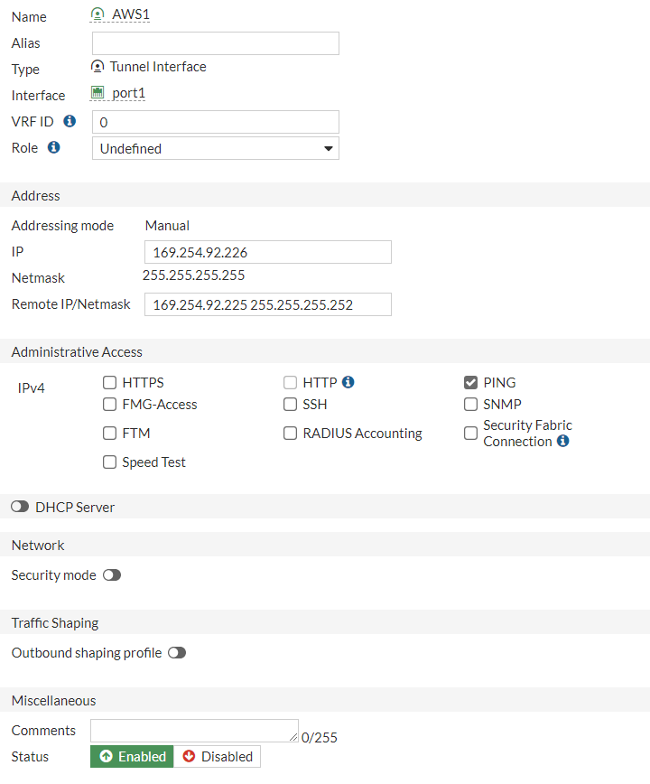
Configure Tunnel interfaces
A tunnel interface is configured to be the logical interface associated with the tunnel.
As defined in #3: Tunnel Interface Configuration we should configure the addresses accordingly:
a. IP : 169.254.92.226
b. Remote IP: 169.254.92.225/30
c. Select Ping
d. Administrative Status: Up
e. Select Ok.
Go to Networks > Interfaces > expand the physical interface attached to the tunnel interfaces and click on those tunnel interfaces:
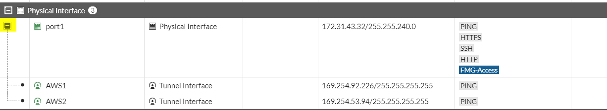
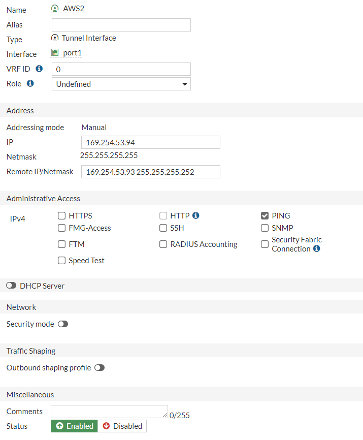
do the same for the second interface:
a. IP : 169.254.53.94
b. Remote IP: 169.254.53.93/30
c. Select Ping
d. Administrative Status: Up
e. Select Ok.
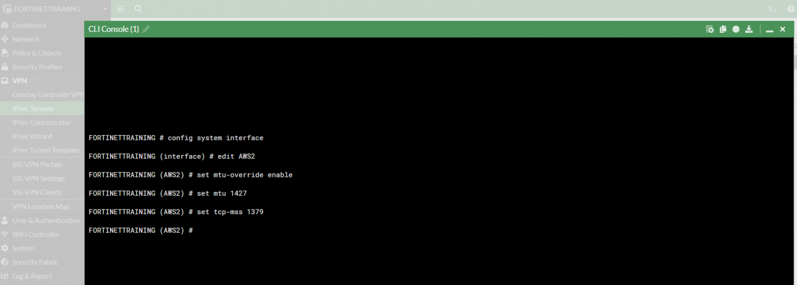
To set the MTU and MSS as reported in the template conf:
!You can set MTU and MSS on the tunnel by performing this from the CLI:
config global
config system interface
edit "vpn-093bd262ad8d9a8b4-0" ! This name will be the same as the VPN tunnel name
set mtu-override enable
set mtu 1427
set tcp-mss 1379
next
end
Open the CLI Console
and configure both interfaces (AWS1 and AWS2):
Configure BGP:
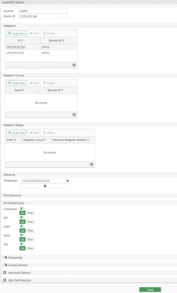
Go to Network > BGP, and configure accordingly to the template conf:
a. Local-AS : 65000
b. Router-ID: 3.125.234.186
c. Click Apply
d. Neighbor -> Create New:
-
IP: 169.254.92.225 -
Remote AS: 64512 -
Click Add/Edit
and
a. Local-AS : 65000
b. Router-ID: 3.125.234.186
c. Click Apply
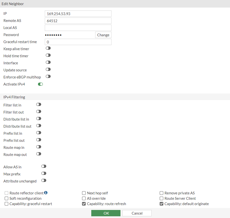
d. Neighbor -> Create New:
-
IP: 169.254.53.93 -
Remote AS: 64512 -
Click Add/Edit

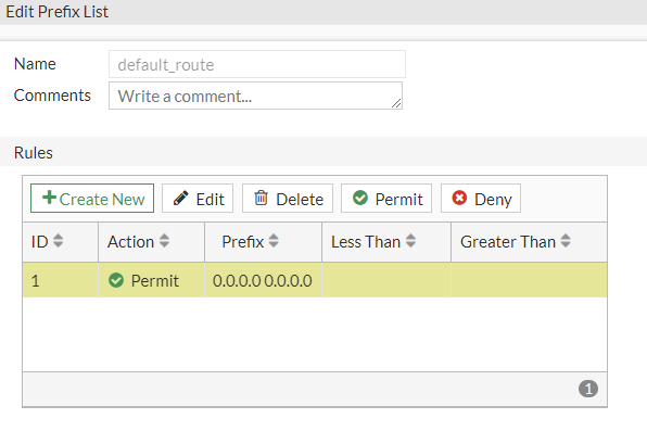
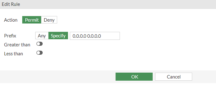
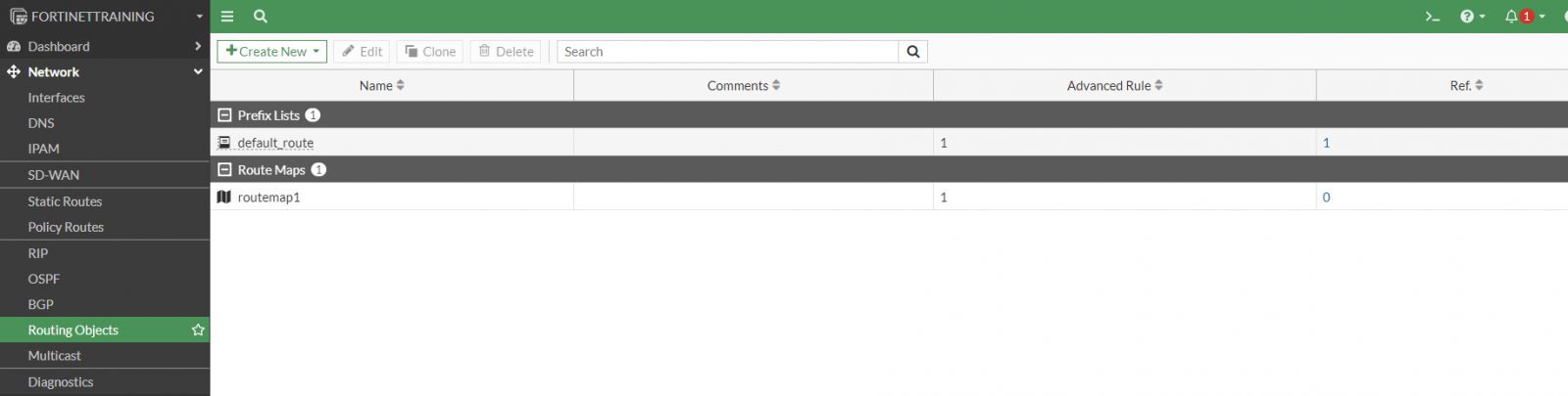
Now configure the Prefix Lists and Route Maps needed for BGP.
Go to Network > Routing Objects:
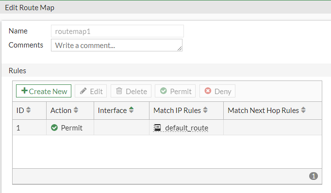
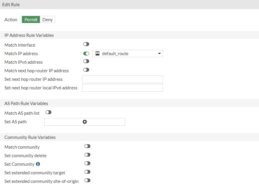
so that at the end we will have this configuration:
We can also use this script to configure the full BGP section:
config router bgp
set as 65000
config neighbor
edit 169.254.92.225
set remote-as 64512
end
end
end
config router bgp
config neighbor
edit 169.254.92.225
set capability-default-originate enable
end
end
end
config router prefix-list
edit "default_route"
config rule
edit 1
set prefix 0.0.0.0 0.0.0.0
next
end
end
end
config router route-map
edit "routemap1"
config rule
edit 1
set match-ip-address "default_route"
next
end
next
end
config router bgp
config network
edit 1
set prefix 172.31.0.0 255.255.0.0
next
end
config router bgp
set as 65000
config neighbor
edit 169.254.53.93
set remote-as 64512
end
end
end
config router bgp
config neighbor
edit 169.254.53.93
set capability-default-originate enable
end
end
end
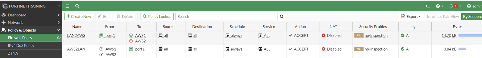
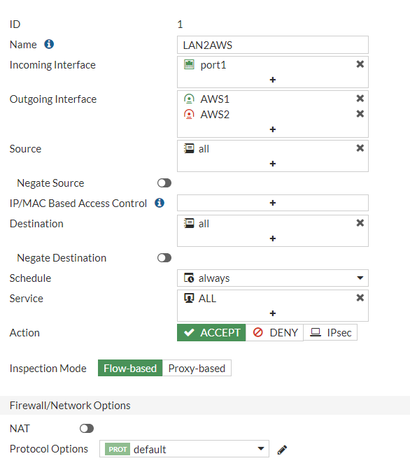
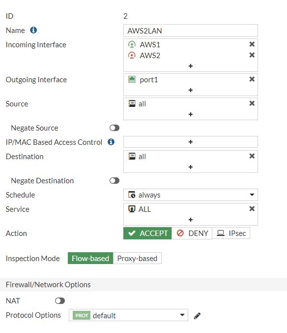
Configure Firewall policies
We need to create at least two firewall policies permitting traffic from local network to VPN subnet and vice versa:
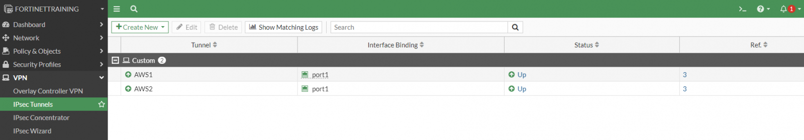
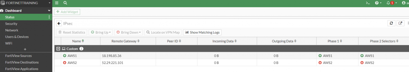
Testing
Now the IPSec tunnels will both be up and running:
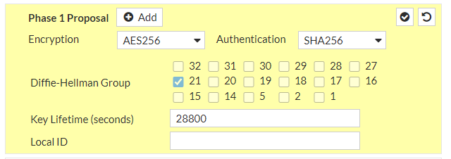
Increase the security in the VPN connection
Now, since AWS side VPN tunnels support better security, we can adjust Fortinet configuration accordingly. We can use:
AES256 instead of AES128
SHA-256 instead of SHA1
Diffie-Hellman group >21 (up to 24) instead of DH2
FortiOS 7.2 supports DH32, but we should use latest version supported by both sides, namely DH21
Let’s adjust Fortinet configuration:
VPN > IPsec Tunnels > edit both tunnels with the new parameters:
and
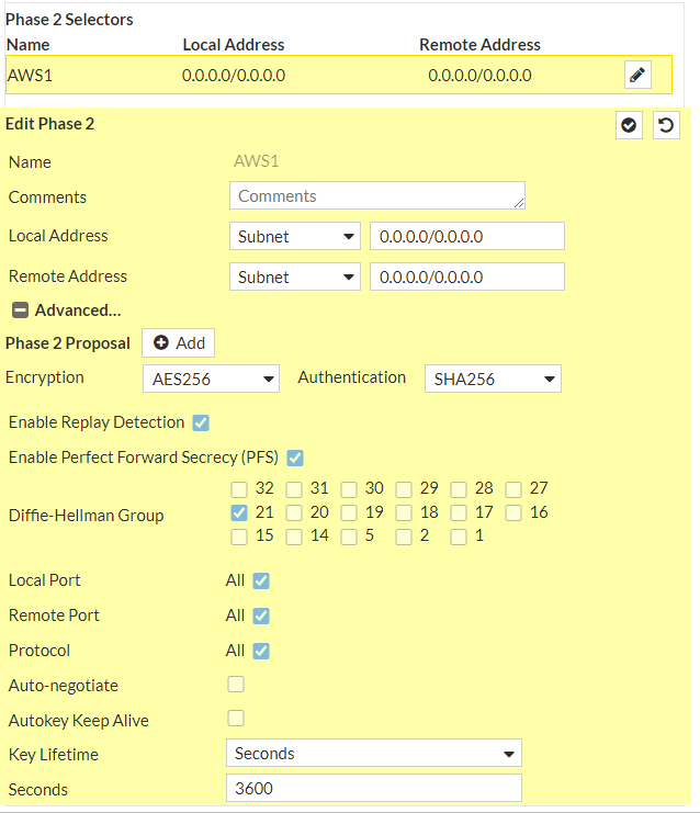
Now the IPSec tunnels will be up and running with maximum security:
We have done!
For more information and support please contact our UCCS Onboarding Team.