Configuring Palo Alto Next Generation Firewall
Version tested: Palo Alto Next Generation Firewall versione 10.2.2
In this section we will refer to the configuration file you obtained from our UCCS Onbording team as “template conf” and will explain how to use its contents for configuring PaloAlto NGFW.
As a reference for this guide, here is the full AWS file: Palo Alto PANOS 7.0+ ikev2.txt
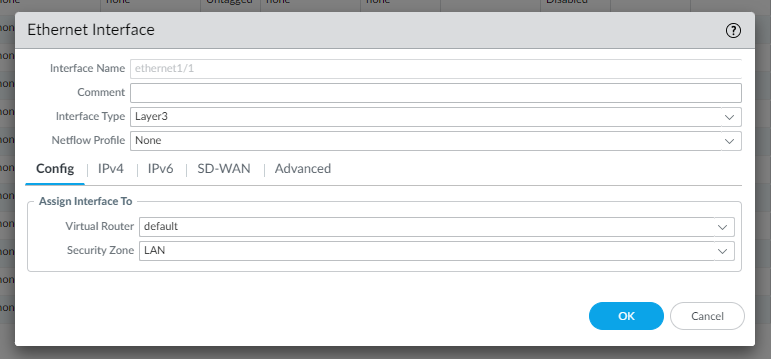
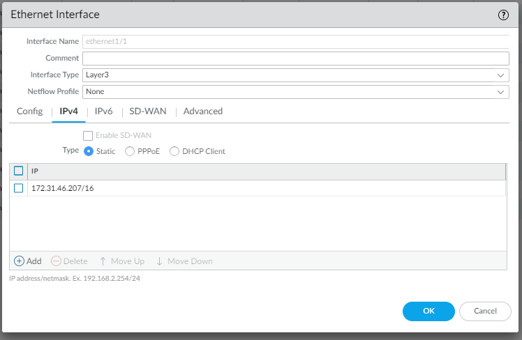
Configure the Network to be used by LAN devices to connect through VPN:
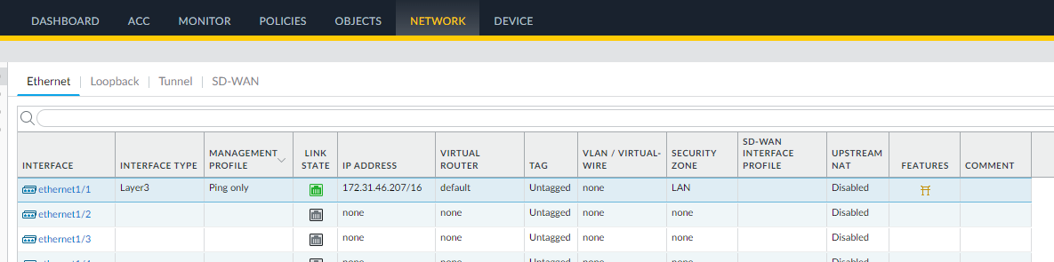
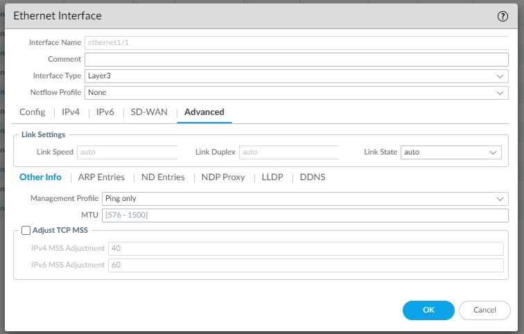
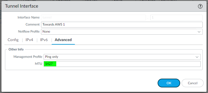
In the Advanced configuration you can can select a Management Profile “Ping only” you create before as follow:
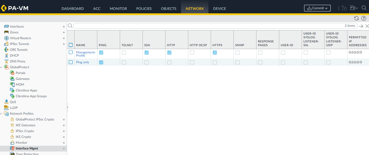
There is also a Mangement-Profile, assigned to MNGT network, that allows you to administer the firewall.
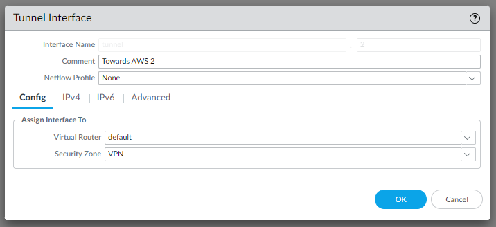
Configure the network Tunnels to be used to connect through VPN:
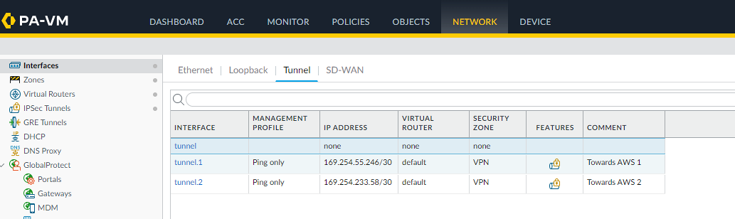
Since AWS will create 2 different tunnels for high availability reasons, we create a tunnel.1 and tunnel.2 interface to be used.
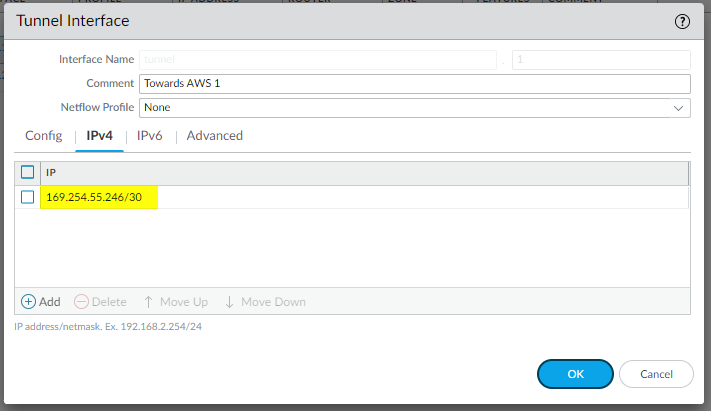
Looking at the template conf #3: Tunnel Interface Configuration (for both IPSec Tunnel #1 and IPSec Tunnel #2) you can see the ips used inside the tunnels to be configured:
edit network interface tunnel units tunnel.1
set ip 169.254.55.246/30
set mtu 1427
top
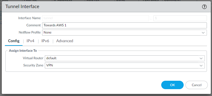
So we configure the tunnel interface accordingly in Network | Interfaces | Tunnel:
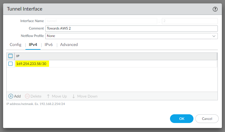
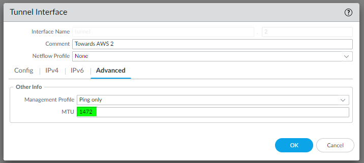
and the same for IPSec Tunnel #2:
edit network interface tunnel units tunnel.2
set ip 169.254.233.58/30
set mtu 1427
top
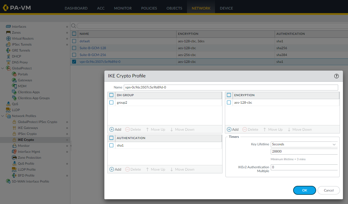
Configure the IKE Crypto profile
Looking at the template conf #1: Internet Key Exchange (IKE) Configuration
configure
edit network ike crypto-profiles ike-crypto-profiles vpn-0c96c3507c5e9b89d-0
set dh-group group2
set hash sha1
set lifetime seconds 28800
set encryption aes-128-cbc
top
so let’s create it in Network | Ike Crypto | Add:
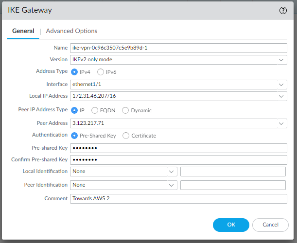
Configure the IKE gateways
Looking at the template conf #1: Internet Key Exchange (IKE) Configuration, in “IKEv2 only mode“ section we can find all the needed values:
edit network ike gateway ike-vpn-0c96c3507c5e9b89d-0
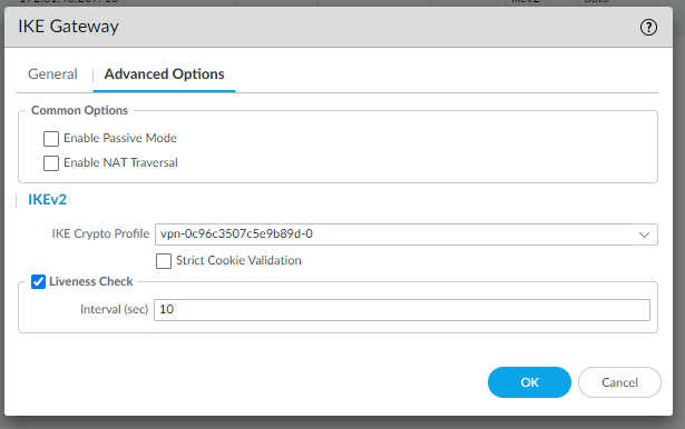
set protocol version ikev2
set protocol ikev2 ike-crypto-profile vpn-0c96c3507c5e9b89d-0
set protocol ikev2 dpd enable yes interval 10
set authentication pre-shared-key key <PRESHAREDKEY>
set protocol-common nat-traversal enable yes/no
set protocol ikev2 require-cookie yes/no
set local-address ip 3.125.234.186
set local-address interface ethernet1/1
set peer-address ip 3.74.203.82
top
so let’s create them in Network | Network Profiles | Ike Gateways | Add:
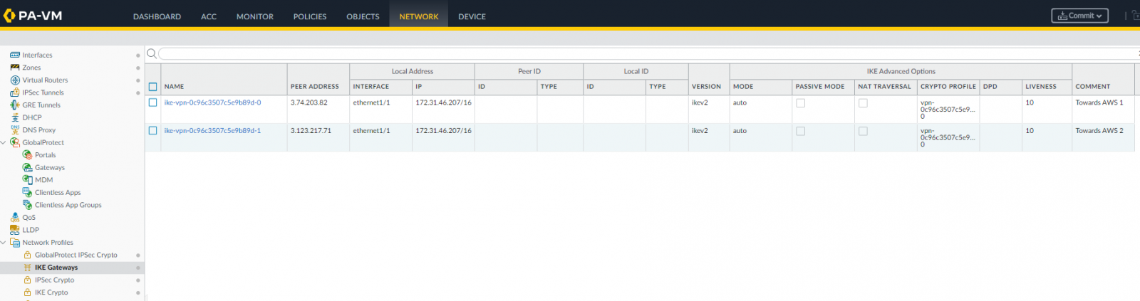
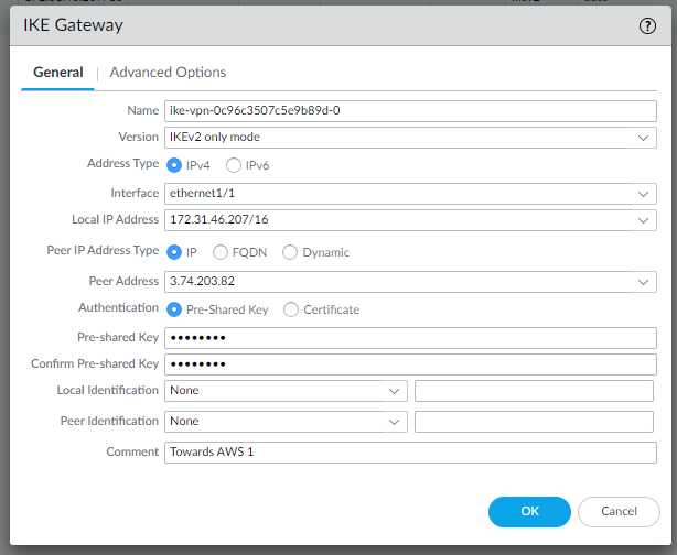
Pay attention to use the correct Local IP Address.
We use our LAN address, while in the AWS file it’s reported the public IP address.
and for the second IKE gateway:
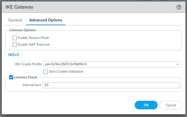
We use the same IKE Crypto Profile since they are the same for both gateways.
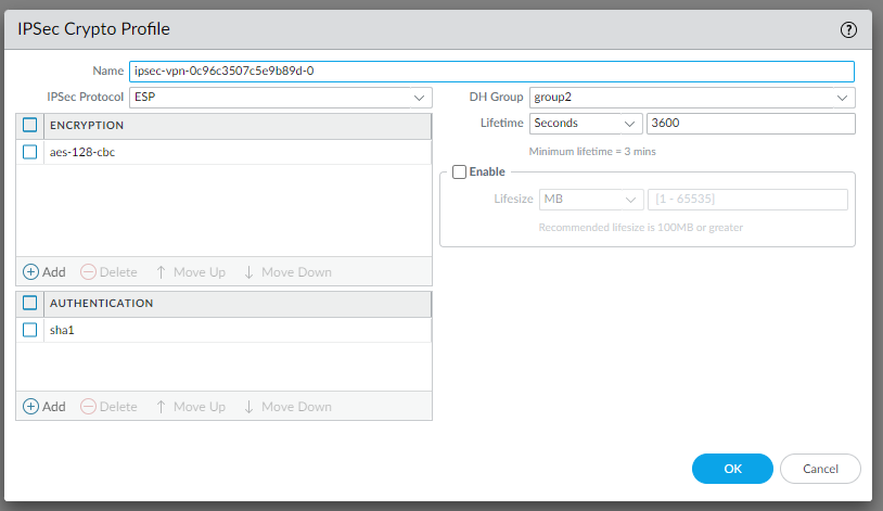
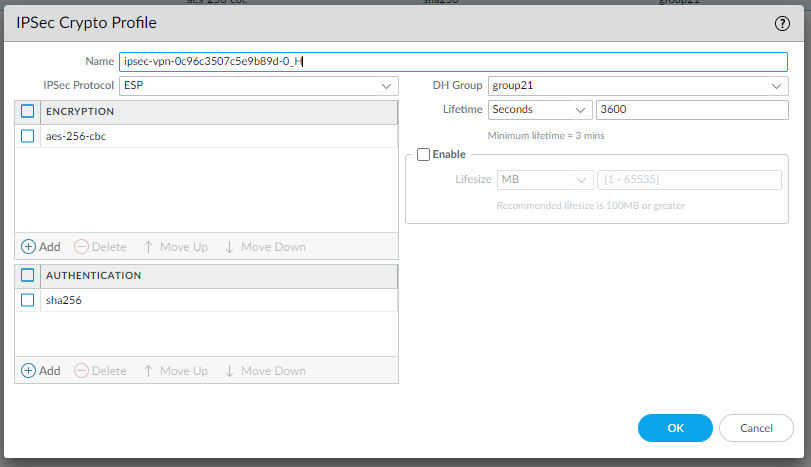
Configure the IPSec Crypto
Looking at the template conf #2: IPSec Configuration:
edit network ike crypto-profiles ipsec-crypto-profiles ipsec-vpn-0c96c3507c5e9b89d-1
set esp authentication sha1
set esp encryption aes-128-cbc
set dh-group group2
set lifetime seconds 3600
top
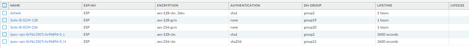
so let’s create it in Network | Network Profiles | IPSec Crypto | Add:
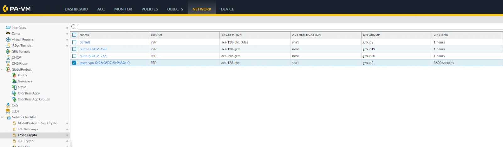
We use the same IPSec Crypto Profile since they are the same for both IPSec tunnels.
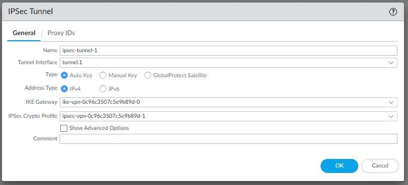
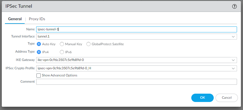
Configure the IPSec Tunnels:
Looking at the template conf #3: Tunnel Interface Configuration
edit network tunnel ipsec ipsec-tunnel-1
set auto-key ipsec-crypto-profile ipsec-vpn-0c96c3507c5e9b89d-0
set auto-key ike-gateway ike-vpn-0c96c3507c5e9b89d-0
set tunnel-interface tunnel.1
set anti-replay yes
top
so let’s create them in Network | IPSec Tunnels | Add:
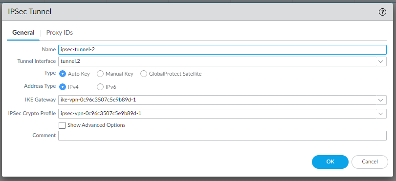
and
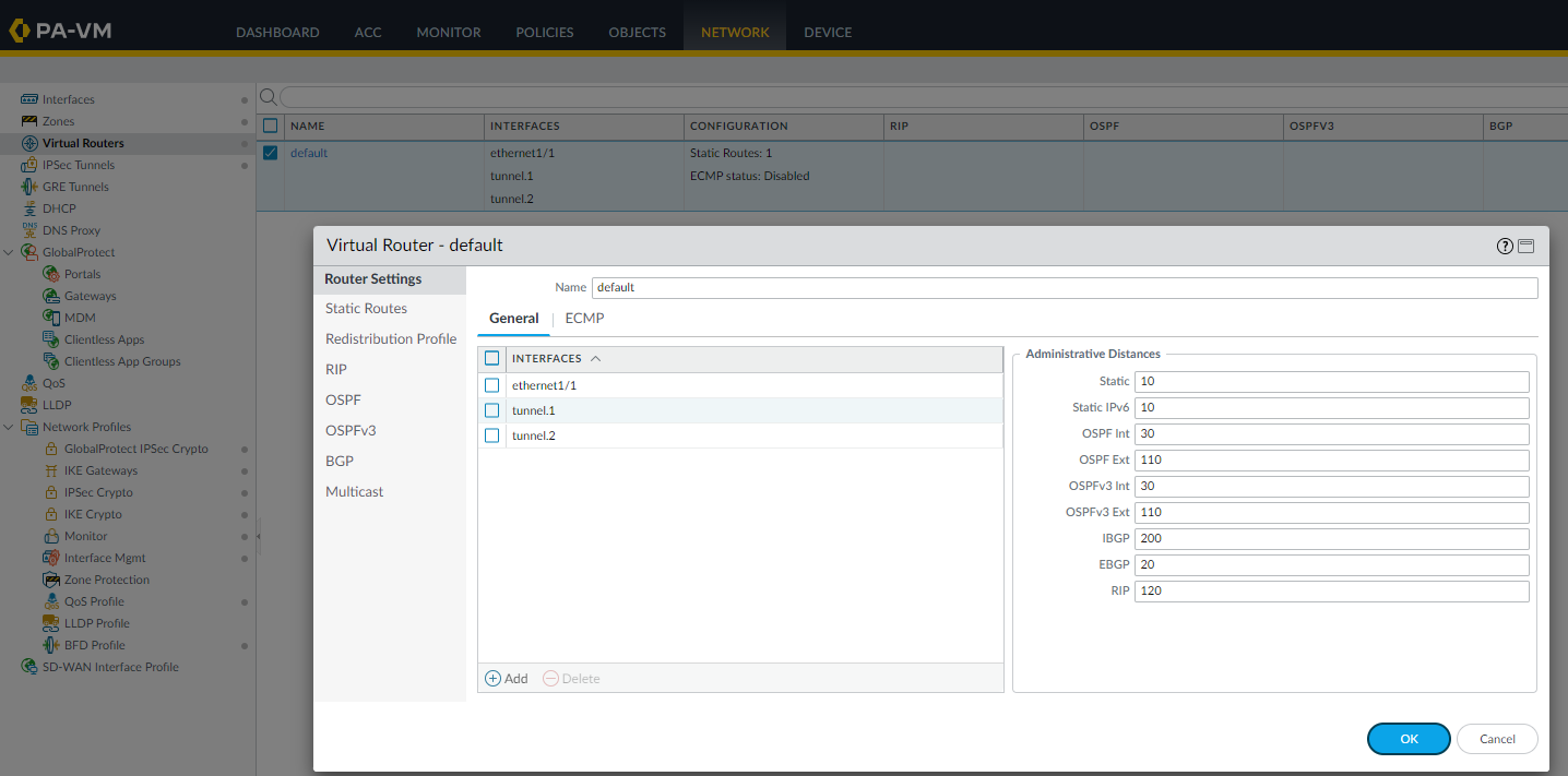
Configure the Virtual router - default
Tunnel interface needs to be associated to a virtual router, we are using default as an example, please adjust accordingly:
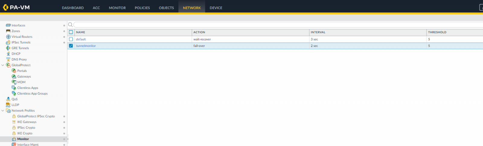
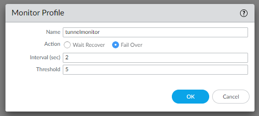
Create a monitoring profile “tunnelmonitor”:
Create a monitor to failover traffic between tunnels.
In Network | Network Profiles | Monitor | Add:
Create a policy based routing
After creating the monitoring profile “tunnelmonitor”, to allow traffic during failover between tunnels, we use policy based routing:
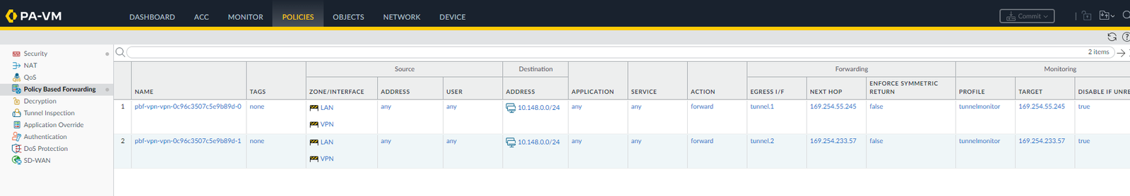
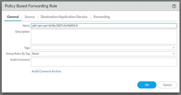
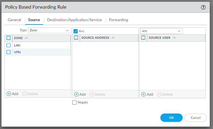
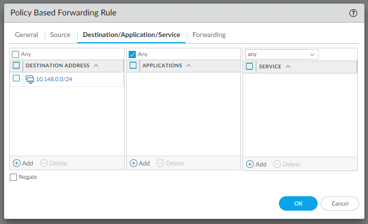
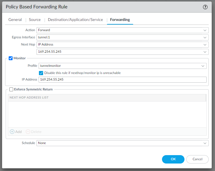
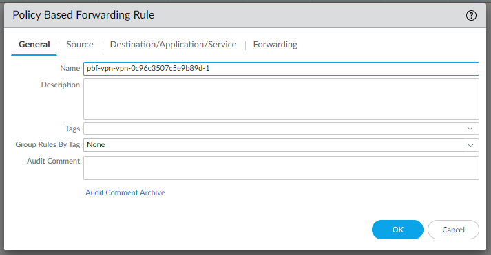
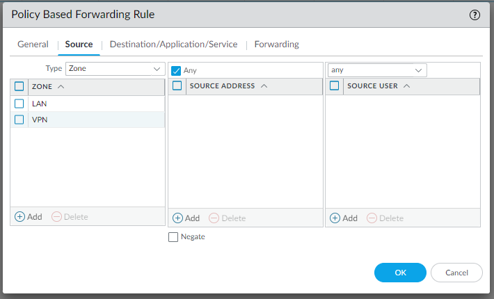
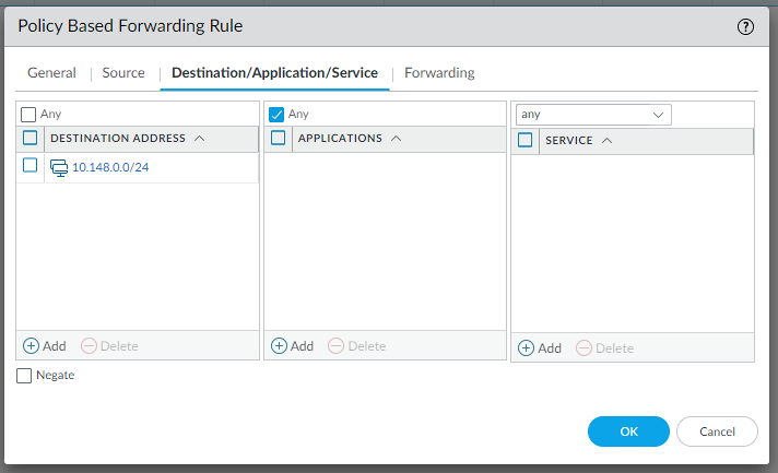
Create PBFs as described in the template conf #4 Static Route Configuration:
edit rulebase pbf rules pbf-vpn-vpn-0c96c3507c5e9b89d-0
set action forward nexthop ip-address 169.254.55.245
set action forward egress-interface tunnel.1
set action forward monitor profile tunnelmonitor disable-if-unreachable yes ip-address 169.254.55.245
set source LAN-CIDR source-user any destination VPC-CIDR application any service any
set from zone trust
set disabled no
top
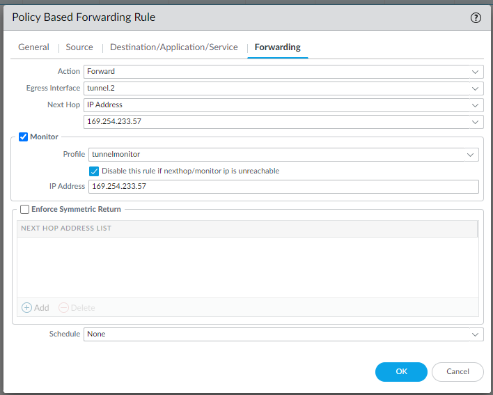
And do the same for the configuration in IPSec Tunnel #2 | #4 Static Route Configuration:
edit rulebase pbf rules pbf-vpn-vpn-0c96c3507c5e9b89d-1
set action forward nexthop ip-address 169.254.233.57
set action forward egress-interface tunnel.2
set action forward monitor profile tunnelmonitor disable-if-unreachable yes ip-address 169.254.233.57
set source LAN-CIDR source-user any destination VPC-CIDR application any service any
set from zone trust
set disabled no
top
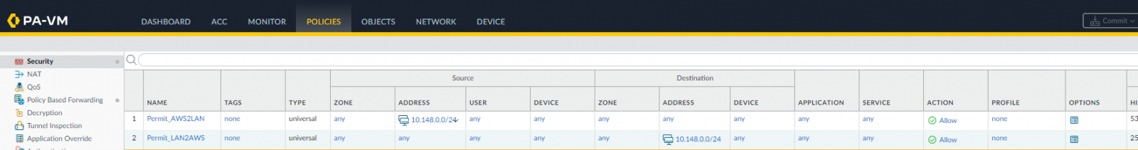
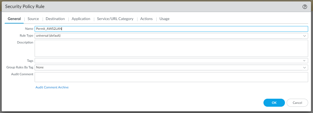
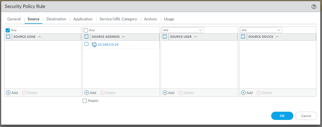
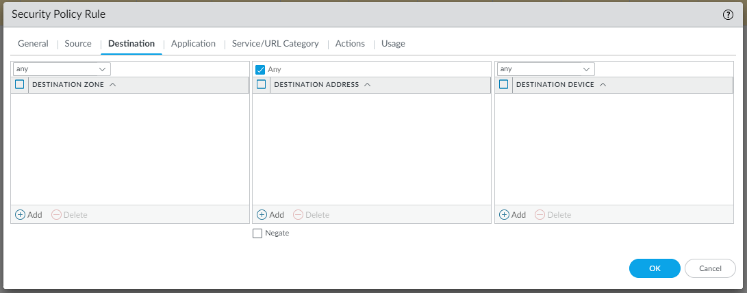
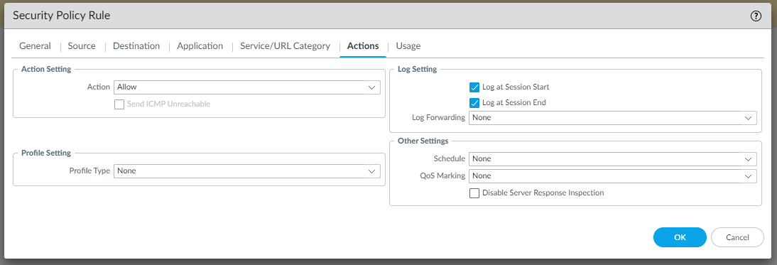
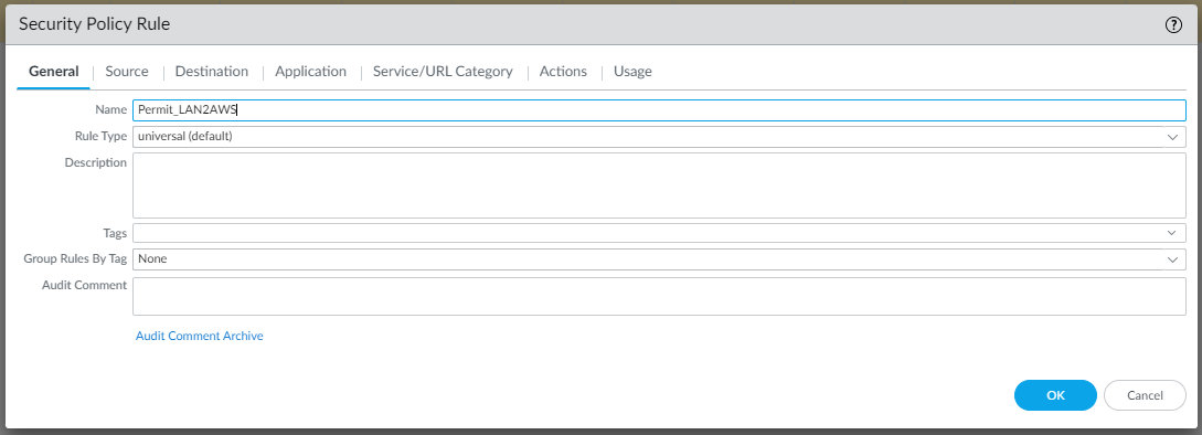
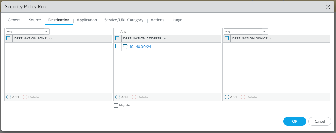
Configure Security settings:
To allow LAN traffic to reach the VPC in AWS and vice versa, we need to create two Security rules as follows (Policies | Security | Add):
and


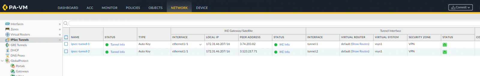
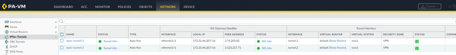
Testing
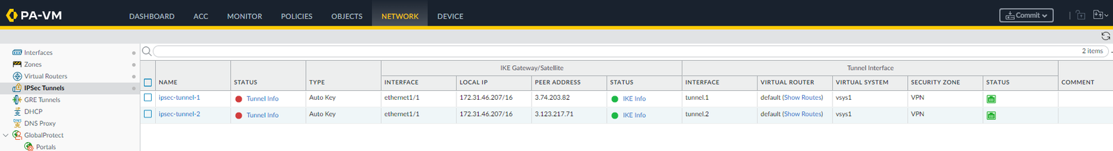
Going back to Network | IPSec Tunnels we should be able to see both up and running:
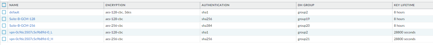
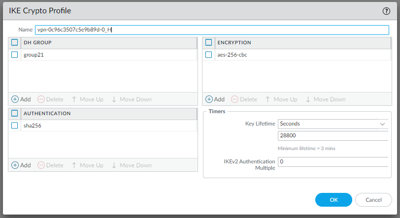
Increase the security in the VPN connection
Now, since AWS side VPN tunnels support better security, we can adjust Palo Alto configuration accordingly. We can use:
-
AES256 instead of AES128
-
SHA2-256 instead of SHA1
-
Diffie-Hellman group >21 (up to 24) instead of DH 2, Palo Alto supports DH21
-
IKEv2 whenever possible
Let’s adjust Palo Alto configuration:
IKE Crypto profile
IPSec Crypto profile
Change IKE gateways with the new IKE Crypto profile:
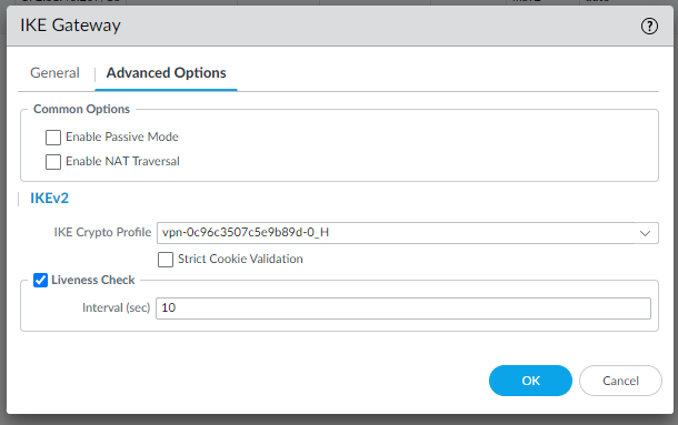
And the IPSec tunnel profiles:
Now the IPSec Tunnels should be up and running with maximum security:
We have done!
For more information and support please contact our UCCS Onboarding Team.